













































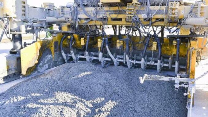
Slipform paving crews do not consolidate concrete the way flatwork crews do with a handheld poker. On a mainline or barrier pour, vibrators ride with the paver, sit in fixed lanes across the slab, and keep running while the machine advances. Spacing, head size, hydraulic flow, and vibration rate have to stay inside the influence zone the mix and the agency expect—or you leave soft spots, honeycombing, and density failures that show up in cores long after the train has moved on.
This guide is a field checklist for spacing and monitoring hydraulic paving vibrators so highway slabs hit density spec. It is not a brand bake-off and not a substitute for the project’s consolidation specification. Treat manufacturer influence diameters, VPM targets, and monitoring logs as tools you verify against the mix and the inspector’s acceptance criteria.
Why Slipform Vibrator Spacing Is Different From Handheld Consolidation
Handheld consolidation is opportunistic: the operator chooses insertion points, dwell time, and withdrawal based on what the pour looks like in front of them. Slipform consolidation is geometric. Heads are mounted across the width of the paver, stay immersed in low-slump paving concrete, and travel at the machine’s forward speed. Overlap between adjacent influence zones has to be planned before the first load arrives—not guessed after a soft streak shows in the fresh surface.
Agency and airport practice often drives center-to-center spacing tighter than a casual “cover the width” layout. Published guidance tied to monitored paving commonly keeps vibrator centers no more than about 16 inches apart so influence zones overlap under the mix and travel speed you are running. Wider spacing that works on a high-slump wall pour will not automatically work on a stiff mainline mix moving at several feet per minute under the paver.
Travel speed multiplies the problem. At roughly 4 feet per minute of forward travel, a cubic foot of concrete spends on the order of 10 seconds under vibration—plenty of energy if heads are alive and spaced correctly, and a fast way to under-consolidate if a dead head sits in the pattern or spacing leaves a gap. Spacing is therefore inseparable from VPM, head condition, and how fast the superintendent wants the train to run.
Matching Head Size and Influence Diameter to Slab Thickness and Mix
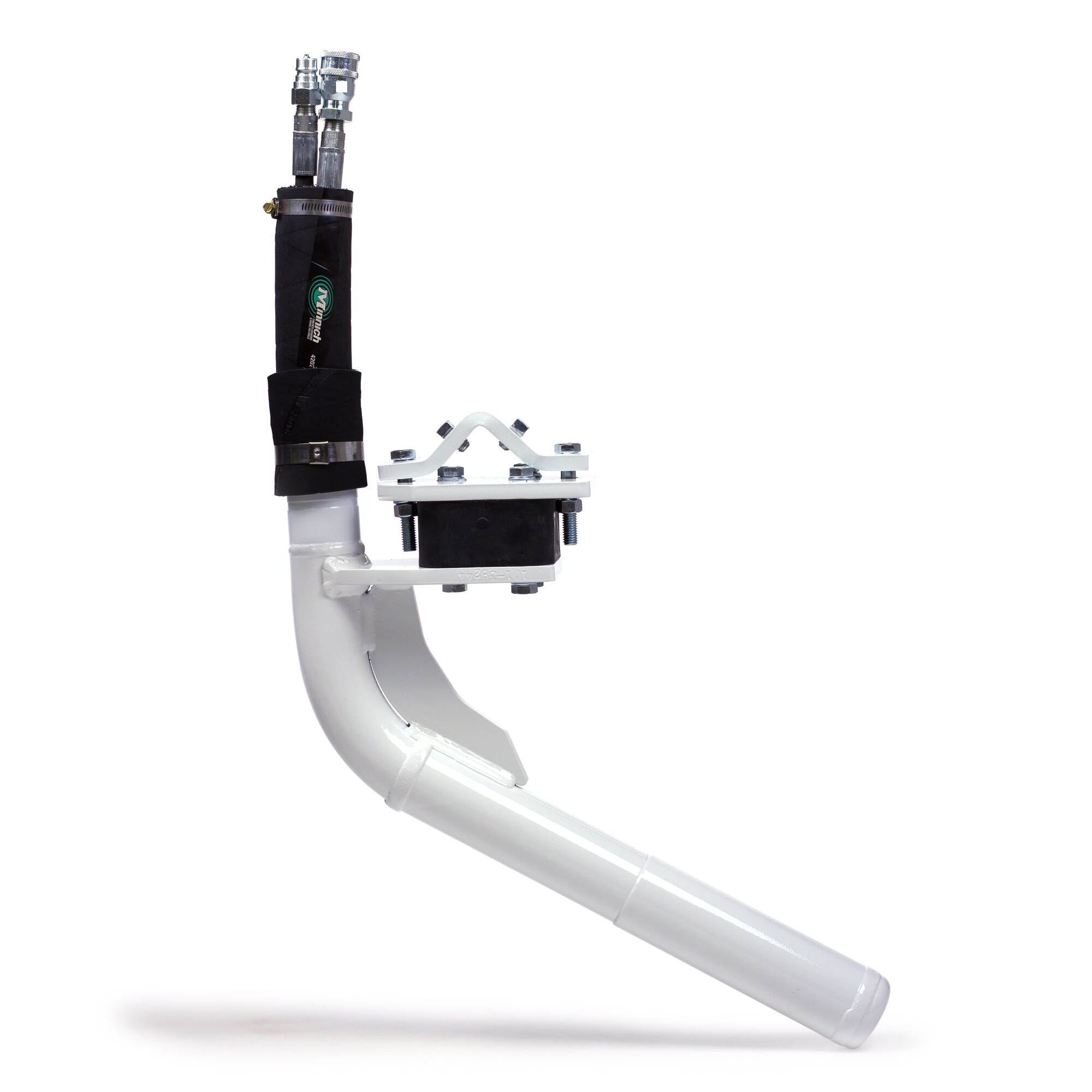
Head diameter and published influence diameter are starting points, not magic numbers. Manufacturer data for hydraulic paving heads commonly lists influence diameters that shrink as VPM drops—for example, a 2-5/8-inch-class head may show a larger influence diameter near 10,500 VPM than at 8,000 VPM. Thicker slabs and coarser, stickier paving mixes need that influence verified in the field; thinner barrier sections may favor smaller heads that fit the mold and still overlap.
Match the head to the section you are paving today. Mainline slabs and wide panels usually want the larger paving head class; barrier and other tight molds often need a setup that fits the form without forcing awkward hose routes. Isolator style matters for the same reason: block isolators used on many mainline mounts reduce concrete build-up and help limit vibration transfer into the paver frame, while two-isolator arrangements are often chosen where space inside a barrier mold is tight.
Do not invent influence numbers when the mix design, aggregate, or temperature changes mid-project. Re-check spacing against the current mix’s response—paste content, slump, and temperature all change how far vibration travels—then confirm with density or consolidation checks the agency already requires. If the influence you assumed last month no longer overlaps at today’s VPM, tighten spacing or adjust speed before you argue with the core drill.
Setting Hydraulic Flow, Pressure, and VPM Targets Before the First Pour
Hydraulic paving vibrators live or die on supply. Flow, pressure, and back pressure have to keep every head in the band the manufacturer rates for that model—and inside the VPM window the project specification calls out. Typical published operating windows for a common 2-5/8-inch hydraulic paving head include maximum flow on the order of 4 GPM, normal operating pressure in a band around 800–1,300 PSI, and a hard limit on back pressure (often around 150 PSI maximum) that crews ignore at their peril.
Set the manifold and flow controls before the first load, not after the train is already half a station into the pour. Confirm that every circuit that feeds a head can deliver the flow the head needs at the pressure the motor wants. A tachometer or the paver’s vibration monitor is how you prove VPM—not the sound of the hose or a hopeful glance at a gauge that is shared across too many circuits.
Write the day’s target VPM beside the mix and the travel-speed plan. Airport and highway work increasingly treat controlled frequency as a contract requirement, not a nicety. If the specification gives a range, stay inside it; if the monitor shows a head drifting low while neighbors sit on target, treat that as a dead or starving head until you prove otherwise.
Using Vibration Monitoring Data to Catch Dead Heads Before They Create Soft Spots
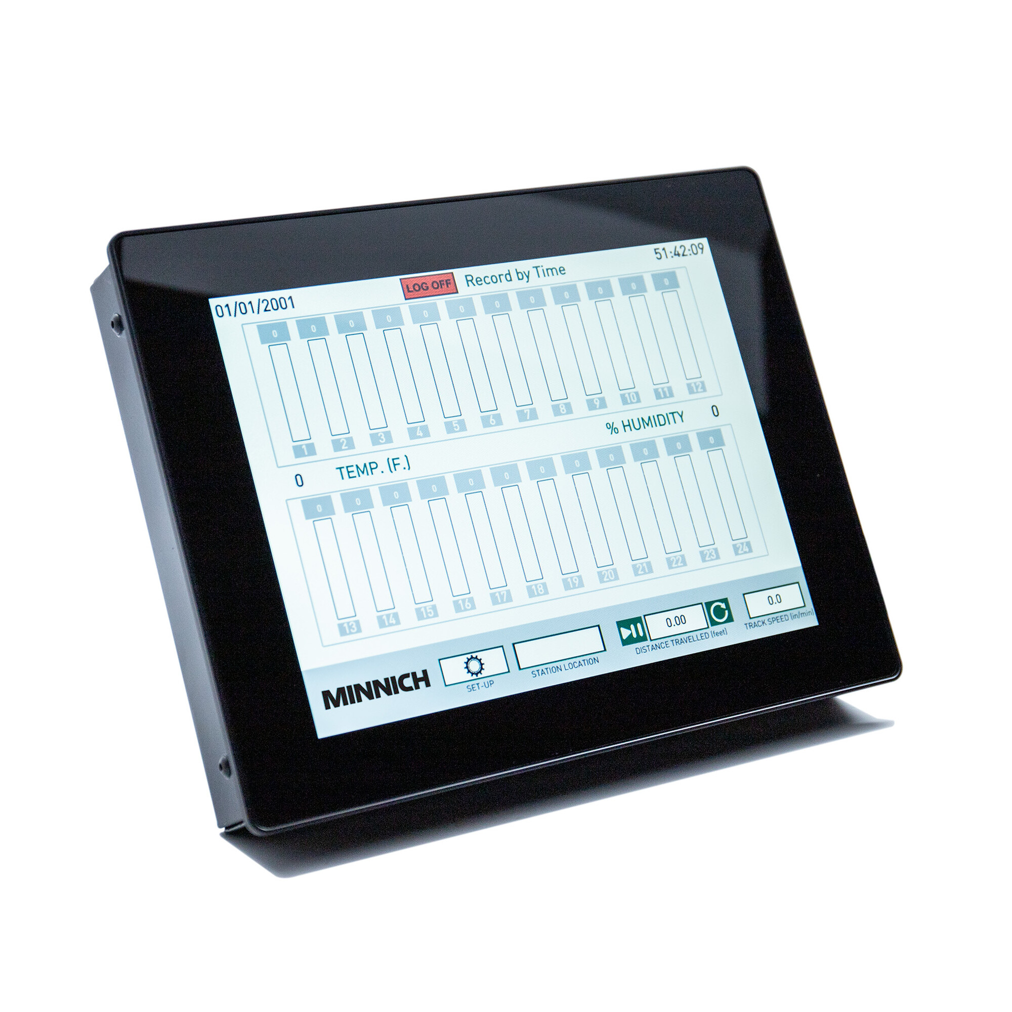
Real-time monitoring turns spacing theory into a live quality-control loop. Systems that display per-head VPM, machine travel, and station location let the operator see a dead or weak head while concrete is still plastic—before the soft streak becomes a density failure. Logging by time or distance also gives the QC team a record that matches cores and ride quality later.
Use the monitor the way a plant uses a batch ticket: glance is not enough. Assign who watches the screen during the pour, what yellow/red thresholds mean for stopping or slowing the train, and how quickly a spare head or hose swap gets into the pattern. A head that reads zero while its neighbors hum is not a paperwork problem; it is an unconsolidated lane the width of that influence gap.
Manufacturers of hydraulic paving vibrators and monitors—including Minnich Manufacturing—publish influence diameters, flow/pressure windows, and monitoring options so crews can set spacing and VPM against documented product data instead of folklore. Pair that data with the project’s consolidation and density acceptance criteria, and keep the logs with the day’s paving report.
End-of-Day Isolator and Hose Checks That Prevent Next-Morning Downtime
Most next-morning vibrator failures started the evening before. Concrete packed around isolators, abraded hydraulic hose, loose mounts, and ignored back-pressure symptoms become dead heads after the first station of the next shift. End-of-day discipline is cheaper than mid-pour chaos.
Walk the bar after washdown. Check isolators for cuts, chunking, and concrete build-up that will cook the rubber overnight. Inspect armor-coated hydraulic hose for abrasion at clamp points and anywhere the hose rubs the paver frame. Confirm mounts are tight, fittings are dry and clean, and spare heads, isolators, and hose assemblies are on the truck—not “back at the yard.”
Close the loop with a quick functional check before the next pour: bring heads up to target VPM on the monitor or tachometer, watch for slow starters, and fix the weak circuit before concrete hits the grade. Consistency beats heroics. The slab only gets one chance at consolidation while the paver is overhead.
Final Thoughts
Highway density specs do not care how loud the paver sounded. They care whether every lane across the slab saw overlapping influence at the right VPM for the mix and travel speed you ran. Space heads for overlap, set hydraulics so every motor can hold target, watch the monitor for dead heads, and finish the day with isolator and hose checks that keep tomorrow’s first station honest. Do that as a routine—not a scramble after a failed core—and slipform consolidation stays a controlled process instead of a gamble.