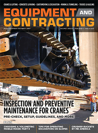
View the complete article here.
The information in this article focuses on the proper inspection of embankment construction, with the goal of ensuring a solid, good, lasting embankment. Not only will the embankment withstand the test of time, but it also ensures durability and safety for everyone using the highway.
Test Fills
Constructing a test embankment may be helpful and in some situations, necessary to determine the best process for designing and constructing an embankment. A test fill should determine a number of issues, including the best type of compaction equipment, lift thickness, and the number of passes necessary; maximum rock sizes for the fill; the physical properties of the in-place fill; and the amount of degradation occurring during hauling, placing and rolling. Any information gained during this process can both improve the ultimate design of the embankment and can influence the cost of the structure.
To properly conduct a test fill, construction control should be precise. It is often performed in conjunction with a test quarry to ensure that the material used during the testing process is the same as what will be produced during excavation. Records should be kept of all significant data, such as radiation, particle breakage, settlement, and lift thickness. In this way, contractors will have a clear set of data that can be relied upon when making decisions on constructing an embankment.
Rock Embankment
When rocks cannot be removed from an embankment without blasting, then they must be removed through a process known as rock excavation. During excavation, all stones and boulders sized 1/2 cubic yard or larger are removed.
After excavation, rock fill can then be used in the embankment; however, there will be large voids between the chunks of rocks that must be filled with fines. When a rock fill is used, there are large voids between the rock chunks that must be filled with fines. Fines, or coarse rock dust, will fill the sides and top of the embankment, but large voids may remain inside of the embankment. Particular care should be paid to this issue to ensure that no voids remain. As a general rule, deformations are not a problem, as the rock pieces will remain intact due to friction and interlocking between them.
- Lift Requirements:
- Voids within the embankment are filled with small sized stones. Larger stones can be distributed to reduce the risk of pockets, however these stones should not be nested within the embankment.
- The target density of the top 2 feet of the embankment can be achieved by using a suitable material that is compacted. Avoid the use of shale or shale-like material for this area of the embankment.
- If the embankment depth is greater than 5 feet and is composed of rock, then the deposited rock should not exceed the size of the material being placed. Deposited rock should never exceed 4 feet in size.
- For embankments that are 5 feet or less deep or for embankments where the placed material includes something other than just rock, then the placed material should not exceed the top size of the placed rock. The placed material should never be greater than 2 feet to ensure stability.
- During the last lift, the voids should be sufficiently closed, or they must be chocked using suitable material (like small broken stones). Compaction is necessary during this last lift, with the level of compaction dependent on the materials used.
- If shale is used as a rock embankment, written permission is required from the site owner.
- Compaction Methods:
- If the rock used in the embankment is large enough to perform density tests, then crawler-tread equipment should be used to compact the material. Alternatively, approved vibratory equipment can be utilized — or both methods can be used together.
- All rock must be compacted uniformly, which can be achieved by successive passes with tread areas overlapping.
Soft Rock and Shale Embankments
In embankments composed of rock fill with rocks that weather quickly, there is a potential for the rocks to become soil. As a consequence, these materials could fall into the spaces between the rocks — leading to significant settlement of the embankment, and ultimately, slope failure. It is for this reason that shale is not recommended; large pieces of shale may settle into bigger voids. Avoiding settlement of rock fill is critical to preventing slope instability and failure.
- Compaction and Lift Requirements
- If soft rock, shale, or shale/soft rock mixtures are used, they should have a maximum loose lift of 8 inches. These mixtures should be compacted at least to a maximum dry density of Optimum moisture content must be identified; from there, the mixture should keep the rock within +1 and -2 percent of that content.
- For compaction, approved equipment should be used. This may include a static tamping-foot roller with each tamping foot projecting a minimum of 6 inches and/or a vibrating tamping-foot roller, with each tamping foot projecting a minimum of 4 inches.
- A light weight deflectometer is used for the compaction measurement.
- To accelerate shale slaking action, water can be applied in the cut. The water should be applied again before compaction and disking. To incorporate the water uniformly, a multiple gang disk should be used, with a minimum disk wheel diameter of 24 inches.
- Generally, embankment lifts should receive at least three passes using the vibratory roller; complete coverage of the area is considered a roller pass. Before the vibratory roller is used, the material should be bladed.
Embankments on Slopes and Hillsides
Before embankments are placed on natural soil slopes, they must be prepared. These methods are also needed if the existing fill slopes are sharper than 4:1. To prepare the slope, benches of a minimum of 10 feet in width are cut into the slopes before the embankment fill is placed. If the natural soil slopes are 4:1 or flatter, then the surfaces must either be deeply scarified or plowed.
Embankment Over Existing Roads
When embankments are placed over existing roadways, specific precautions must be undertaken. There are a number of suggested treatments, including:
- Removing the existing pavement if the upper surface of the existing pavement is located 12 inches below the subgrade elevation of the new pavement.
- Breaking the existing pavement if the upper surface of the existing pavement is located between 12 inches and 3 feet below the subgrade elevation of the new pavement. In this situation, individual pieces of the existing pavement should be broken to less than 1 cubic yard.
- If the existing pavement consists of a concrete base with a hot mix asphalt surface, located between 12 inches and 3 feet below subgrade elevation of the new pavement, then the first step must be to remove the hot mix asphalt. Next, the concrete base should be broken.
- When hot mix asphalt is 12 inches or fewer below or above the required subgrade elevation, the existing pavement should be broken and then removed.
- When the top of the existing pavement is greater than 3 feet below the target subgrade elevation, then the existing pavement can be left in place.
- When an embankment is widened, precautions must be taken. First, any perishable material should be removed. After these materials have been removed, the existing shoulders 2 feet out from the pavement should be completed. Then benches can be cut into the old embankment with a minimum of 4 feet in width, unless otherwise specified. Direct payment is not needed for benching or plowing because the cost should be wrapped in the contract line items.
Compaction Control
Compaction control is an important element of embankment construction. The following factors are essential to the process:
- Typically, a test strip or Geotech lab results will determine the target density of the embankment compaction.
- The control of moisture content should be within +1 and -2 percent of the optimal moisture content. If the material is too wet, then excess moisture should be removed with aeration. Alternatively, if the material is too dry, the moisture content can be boosted with watering and disking.
- After level, uniform layers are placed for embankment material, approved compacting equipment should be used to compact the material. The compacting equipment must have at least three wheels and should be able to create an even, smooth surface.
- Existing clods and lumps are treated or disked using mechanical techniques to ensure they are broken up.
- The required compaction should be obtained for the loose depth of each lift, never exceeding 8 inches.
- The loose depth of lift should not surpass the tamper foot length when a tamping roller is used. At a minimum, each tamping roller foot should be 5 square inches.
- When silty loams, silts, or loessial type soils are used or encountered in embankment construction, the moisture content should be controlled within -3 percent of the optimal moisture content.
- Field compaction tests should be performed on each lift. Before the next lift is placed, the required compaction must be obtained on the previous lifts.
- When gravel soil or sandy soil is used (i.e., the materials have at least 80% or more gravel or sand particles), the moisture level should be within a few percentage points below optimal. This requirement ensures the soils may be compacted to the specified density.
Settlement Control
In some situations, a preliminary investigation may reveal that existing soil beneath the embankment will settle over time due to the construction of a heavy embankment. Here, settlement control is essential. It should include a measurement of the settlement to ensure that an acceptable rate of settlement is occurring.
Geotechnical instrumentation must be included at locations indicated on the plans. The measurement work includes provision of the equipment, installation, maintenance, and reading the results. Placement can be determined as follows:
- Before embankment operations commence, installation must completed with settlement plates (1/2 in. by 3 ft by 3 ft), as well as galvanized pipe (3/4 in. and 2 in.) and couplings for a cover.
- Pipe sections of ¾ inch diameter should be 4 feet in length for the settlement plates. These pipes can be vertically extended from the plate center through the new embankment. The joints should be spot welded. The cover pipe should not be welded to the plate; instead, it should be slipped over the pipe.
- As required in the plans, lateral stakes should also be installed in embankments to help with settlement control. Typically, these stakes are ¾ inch by 4 ft steel rods, which are placed a minimum of 12 inches in the ground.
- Settlement pipes and plates must be be protected during construction, so borrow can be used as embankment material around the equipment.
- When subgrade elevation is achieved for the embankment construction, then settlement stakes should be installed (¾ inch by 4 ft steel rods).
- Elevation readings should be taken on all settlement stakes and settlement plate extension pipes. These reading should be taken at least every 7 days, but may be taken more often depending on the conditions.
- When subgrade elevation is achieved, readings should be obtained from the settlement plate extension pipes, as well as from the settlement stakes. Lateral stakes can be used to measure horizontal movement of the new fill or ground. When lateral movement is identified, corrective measures must be used before work continues.
- Unless otherwise specified in the plans, the new embankment is allowed a settlement period of 3 months after the subgrade elevation construction is complete.
- When subgrade elevation is achieved, readings should be obtained every 7 days until a ¼ inch or less settlement rate is measured for at least 4 weeks consecutively. The Office of Geothermal Engineering may reduce this measurement period. If the readings indicate more than ¼ inch settlement, then the monitoring period will be extended.
- If serious settlement is identified while the embankment is being constructed or during the settlement period, then work must be stopped so corrective measures can be implemented.
View the complete article here.
Why is constructing a test embankment crucial, and what key information does it provide for embankment design?
A test embankment helps determine optimal compaction equipment, lift thickness, rock sizes, in-place fill properties, and potential degradation during hauling, providing crucial data for improved embankment design and cost considerations.
What measures should be taken for settlement control during embankment construction, and why is settlement monitoring important?
Settlement control involves installing settlement plates, lateral stakes, and monitoring pipes to measure settlement rates and ensure stability; monitoring is crucial to identify any significant settlement early, allowing for corrective measures and preventing potential issues.

